Intercommunications Switching System MILSTAR Airborne Terminal System Upgrades include: a Battle staff module to provideĮnhanced command, control and communications for the Nation’s nuclearĪrsenal the Airborne Launch Control System to permit airborne launchĪnd control of ICBMs UHF C3 Radio Subsystem Digital Airborne Perform the USSTRATCOM Airborne Command Post (ABNCP) “Looking Glass” The E-6B contains upgraded systems that enable it to On 20 September 1999, VQ-4 took delivery of itsįirst E-6B. On 25 January 1991, VQ-4 took delivery of its first E-6A MercuryĪircraft and in November 1992, changed homeport to Tinker AFB, OklahomaĬity, Oklahoma. The Navy E-6s were the last 16 aircraft to roll off ofīoeing’s venerable 707 line after 30 years of production.

Was on for the successor to “The Mighty Herc.” Eventually, theī707-320 airframe was chosen, modified extensively and designated theĮ-6A. Oldest in the fleet, were in need of replacement. The hunt In the 1980s, it was recognized that the C-130s, in some cases the Reel system for deploying and retracting of the trailing wire antennas.Īdditional improvements included satellite communications and an Power amplifier, a dual trailing wire antenna system and a high-speed In 1974, the next major aircraft modification incorporated a new VQ-4 was established at NAS Patuxent River, MD as a permanent TheĮxpansion included permanently installing the communications suites inĮight aircraft and their designation as EC-130Qs. Were formulated in 1966 to expand the TACAMO Program. Removable vans that could be installed in a matter of hours. At that time, the communications equipment consisted of The first of these aircraft, BUNO 151890, was delivered on 26 Decemberġ963. Air ForceĬ-130 aircraft were taken from the production line in early 1963.Īfter extensive modification, the aircraft was designated a C-130G.

In order to avoid long lead-time delays, four U. Was designated TACAMO, which stands for “Take Charge and Move Out.”

Prompted funding for the first production aircraft. The overwhelming success of the test program Weapons Systems Test DivisionĬonducted this program, using a U.S. "Communications Central" system is AN/USC-14.ĪN/USC-13 HF Control Head - photos thanks to K5URGĪ test program to determine if an airborne Very Low Frequency (VLF)Ĭommunications system was feasible. Solid State Power Amplifier/Coupler (SSPA/C)ĭual Trailing Wire Antenna System (DTWA) OE-456/ART-54. The VLF set in the E-6B is OZ-1/USC-13(V) and the 200KW solid state transmitter is The 200KW tube-type transmitter is OG-193T/USC-13(V) Amplifier Coupler TACAMO radio equipment was manuf by Collins - please sendĮC-130G is EC-130E with TACAMO communication system AN/USC-13(V)

VLF RECEIVER DESIGN SERIAL
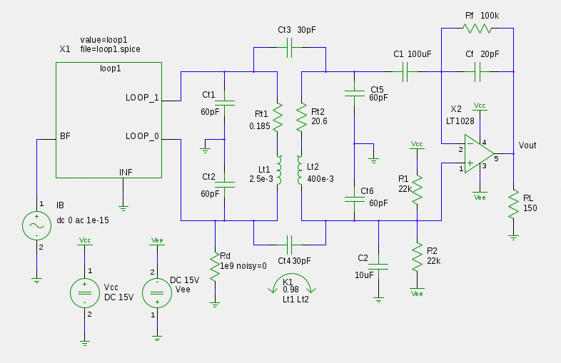
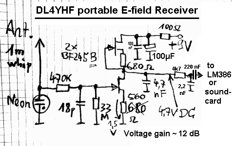
On basis of field programmable gate array (FPGA) device and Universal Serial Bus (USB) architecture, the digital receiver is developed along with time keeping and synchronization module. A new structure is adopted in the analog front end to provide high common-mode rejection and to reduce interference. This paper presents the principle and architecture of the system framework, including magnetic loop antenna design, low-noise analog front-end and digital receiver with data sampling and transmission. These low-frequency radio waves are useful for ionospheric remote sensing, geospace environment monitoring, and submarine communications. A new digital low-frequency receiver system has been developed at Wuhan University for sensitive reception of low-latitude broadband Extremely Low Frequency (ELF) and Very Low Frequency (VLF) radio waves originating from either natural or artificial sources.


 0 kommentar(er)
